Od jakiegoś czasu zastanawia mnie tzw. PLL SSTC - jej budowa, oraz na ile i czym się to różni od zwykłej SSTC ze sprzężeniem zwrotnym.
Znalazłem taki schemat:

Wiem, że mostek tam jest wykonany nie w pełni poprawnie, oraz drivery MOSFET powinny mieć przy sobie kondensatory tantalowe, ale po wprowadzeniu tych poprawek chciałbym na jego bazie zbudować SSTC.
Schemat był tak opisany:
Z tego wynika, że potencjometrem ustawiam początkową częstotliwość a PLL ją przesuwa bardziej w stronę rezonansowej z pomocą antenki. Ale nie do końca wiem na jakiej zasadzie to działa.The capacitor on pins 6 & 7 and the resistors on pin 11 and 12 determine the frequency that the coil runs at. The ratio between R1 and 2 determine how far the oscillator can wander. The 10k potentiometer by pin 9 will adjust the voltage bias on the VCO input and alter the frequency, or if running with feedback adjust the phase angle between input and output. I suggest setting R1 and 2 for a 1.5 ratio during testing, and reduce the ratio as you determine the exact resonance frequency. This makes it much easier to tune for the perfect phase angle. The best way to set up the 4046 is by setting the resistor range first without the gate drivers, half-bridge or secondary. Basically find some ballpark resistor and capacitor values, and then use the potentiometer to see what frequency range you get. The 4046 is rated for an operating frequency of up to 2.7 MHz, so it'll work for practically any coil you may want to make. Audio modulation is also possible by further biasing of the VCO voltage, but I had to run my coil from half-wave rectified mains to keep it from burning up, so it was never implemented. Check Steve Conner's page to see how. Once the circuit is built the potentiometer must be used to tune for resonance.
The phase locking itself works by using an XOR gate to detect the phase angle between the two inputs, pin 3 and 14. The output from the XOR (pin 2) is a PWM signal, and the duty cycle will vary from 0 to 100% as the phase difference between two 50% duty square waves moves from 0 to 180 degrees. A low pass filter is used to get a DC voltage proportional to the PWM signal's duty cycle. This signal is fed into the VCO, which then oscillates at some frequency set by the timing components R1, R2 and C1. (12k, 15k and 330pF in this case) A constant DC bias is also be placed on the VCO input by the 10k potentiometer. Adjusting this bias allows you to roughly set the phase angle.
Szukałem na naszym forum:
Ale to do końca nie wyjaśnia sprawy.Yuri pisze: Cewki pracujące w CW dobrze jest budować wykorzystując układ PLL. Taki układ próbuje wzbudzać oscylacje a potem gdy podejmie sygnał ze sprzężenia dostraja się do niego i umożliwia pracę synchronicznie z rezonansem.
Narysowałem sobie schematy (podzieliłem na moduł MOSFET drivers oraz CD4046)
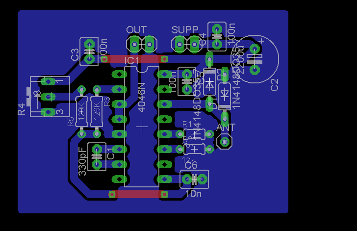
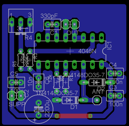
Generator sygnału CD4046:

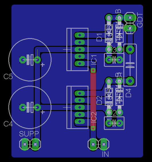
MOSFET drivery:
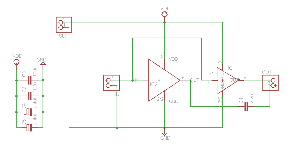
Dodałem kondensatory 100nF oraz tantale i diody schotkiego przed GDT.
Oraz wykonałem layouty płytek:
Sygnał 1:
Sygnał 2:
Sygnał 3:

Drivery 1:
Tu np. nie wiem czy na siłę pchać te kondensatory jak najbliżej nóżek czy bardziej skupić się na tym by masa zalewała odpowiednio każdy pin itp...
Moje pytania:
1. Proszę o przeglądnięcie schematów a potem płytek - co mogę w nich ulepszyć, oraz które wersje layoutów są najlepsze?
2. Czy podział na płytkę DRIVERY MOSFET i płytkę GENERATOR SYGNALU PLL jest sensowny? Kierowałem się tym, że te drivery MOSFET mogę sterować z dowolnego źródła i dalej eksperymentować z innym źródłem sygnału niż PLL.
3. Czy interupter mogę zrealizować poprzez wpięcie jednego tranzystora miedzy OUT płytki z CD4046 i IN płytki z driverami MOSFET? Byłaby to trzecia płytka.
4. Czym różni się działanie takiej SSTC oraz jej efekty od tego drivera (sprzężenie zwrotne z Antenką):

Chodzi mi szczególnie o plusy oraz minusy tego sposobu na PLL względem sposobu z antenką.
5. Czy do tej SSTC mogę bez problemu zastosować półmostek z filtracją? Na oryginalnym schemacie jest jednopołówkowy prostownik...
6. Na ile zmienić rezystor (który?) lub potencjometr, by ten PLL pokrywał zakres częstotliwości 100-300kHz?
7. Po co na oryginalnym schemacie jest rezystor 2W przed GDT a za driverami MOSFET?
Aha, i zamierzam użyć tego sterownika pod takie uzwojenie:
Kod: Zaznacz cały
średnica 11 cm
wysokość 24cm
drut 0,18mm
frez: 220kHz (bez toroida, z toroidem troche mniej)